image

image

Sunday, December 16, 2012

Pit Bot- Making Of: Part 3

so in Part 1 I began carving shapes and making fiberglass parts of the torso and head. In Part 2 I showed how the outer shells were made in carbon fiber. In this part I will show various extra bits like the arms and hover dish..

Extra Parts
for the 'ear' pieces i took a mould of a large cog i found in the workshop, added bits from model tanks and planes to create an interesting mechanical part, then moulded in silicone and cast two versions in resin

in the photo below is also the rear head thruster, a solid resin tube which was turned by hand on a lathe.


the head now has a carbon fiber faceplate and I have been filling and sanding the head shape, getting it ready for painting.


Hover Dish
 
the main hover dish was 3 layers of MDF circles, glued together and then the whole thing was turned on the large Lathe in the workshop. the size of it was dictated by the largest size possible on the vac form machine, which i then used thin clear perspex to form 2 copies of the disk shape, this took quite a while as you have to heat the perspex very slowly so that it doesn't burn on 
 

the 2 dishes were layered on top of each other, the outer one was cut out and would then be the support structure for the 'Thrusters'. the thruster mechanisms were various bits and pieces, the man bits were the large outer casings of cheap headphones from Argos (2 sets collected after they broke from old age- recycling guys!)
working away in my Grannies garage, started arranging all the parts as a kind of dry fit. The grey circular part at the bottom of the bot are disks made from several layers of MDF and Marine Ply, cut on the CNC milling machine and sprayed grey.

Arms
  these details are various bits and bobs found throughout the workshop, then moulded in a flat silicon mould so that i could duplicate them many times. most of these parts would be used on the robots arms..
i built the ams in a way that i would only build one, mould it, and pop out 2 full resin versions. the ivory sections are resin parts, the details above and 2 resin cylinders, turned by hand on a Lathe. the brown parts are the hinges, drawn up in Autocad, 3 layers milled out in MDF by the CNC miller, then glued together.

the forearm and upper arm section was then moulded in  silicone block and then built a plaster case around it to retain its shape.
 

the fingers were don in the same way as the hinges- autocad drawings, CNC mileld and glued together, moulded and then resin version cast.

the left arm was going to be a drill hand, so i lathed some more resin disks, and then moulded and cast out a resin drill head from an old drill i had. the pistons are just alluminium tubes and the white finger covers are just vac-formed styrene parts, based on aother shape turned on the lathe.


Finished hands ready for painting

all the hand parts were washed and cleaned from any grease before painting.


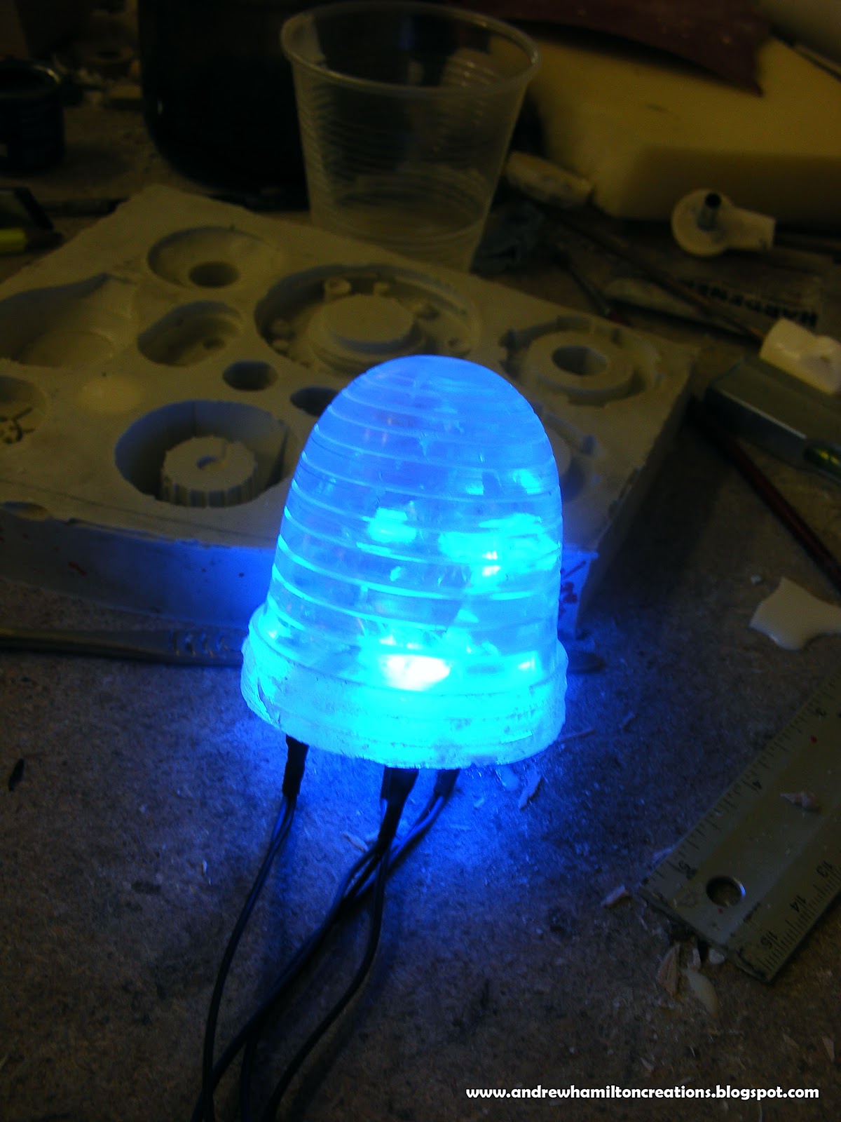
Lighting and Finishing

 one thing I wanted was a really well lit prop, so i spent nearly 2 weeks lighting the bot.
i purchased pre-wired LEDs from a place in England, these are a life saver, no complex electronic maths, just plug them into a 12V power source and bingo-lights! the rear light was a solid lump of clear resin that was turned on the lathe, then 3 lights popped into the underside of it.
heres the head with lights and paint scheme..


beginning a rough assembly of the whole bot. The neck was a bendable coiled wire from a desk lamp.
 
the outer shell was pop-riveted on with aluminium spacers.
 
all the parts in a dry assembly fully painted (except for final weathering.)


final assembly and paint, next stage is adding sponsor logos and realistic weathering. stay tuned!..


Thursday, December 13, 2012

Pit Bot- Making Of: Part 2


Pit Bot: Carbon Fiber

For the exterior shell of the torso and a few other parts i wanted to have a carbon fiber look to them, after some research I decided to do it for real and visited a family friend who runs a canoe and kayak center where he makes carbon fiber paddles. After a quick demo I bought the required materials and scampered back to the workshop. What follows is the process involved.

a rough pattern for the torso shell is layered down with masking tape, the tape prevents the fiber from fraying when cut with a scissors

you can see in this image the plaster carving of the torso shell has been covered in a semi hard foam board, it bends when heated and is very solid when cool. using a heatgun you are able to shape a flat piece of this 'Thermo flex foam' and shape it around your plaster shape. this will form the base material of the carbon fiber, sturdy and very lightweight.

next step is to mix the epoxy resin, if i remember correctly it was a mix ratio of 1:3.
then using a clean layer of plastic underneath your fiber, pour the epox directly on top of it..


after pouring your resin then begin spreading it on the fiber, like buttering a piece of bread..


then you lift the soaked fiber sheet and begin smoothing and shaping it onto the foam. the resin soaks into the foam and creates a very strong bond.


while the resin is still wet the next thing that goes on is a layer of nylon fabric called Peel-Ply.
this fabric basically soaks into the resin and pulls it up away from the fiber, so that the fiber is trapped in a layer of resin between the foam and the peel-ply. the reasons for this are apparent soon..


once the resin dries you then rip the peel ply away, the peel ply does not stick well to the surface but it creates a slightly raised even texture on the dried resin which is easy to sand down and polish. without the peel ply, the resin would settle on the top of the carbon fiber and there would be no allowance for sanding without sanding down into the actual fibers themselves. below is rear torso panel dried with Peel-ply still on..


and here is the same panel with the ply removed


then after a few hours of sanding with wet and dry sand paper you have a very smooth finish.

More to come in Part 3!!